Prologue
Computers are the miracle of the modern age, and have transformed the way we work, think, and live. To most, computers are magical and ‘just work’, a sentiment derived from the boundless effort spent developing wonderful machines and software by computer engineers and scientists.
Computer scientists are magicians in their own right, but modern software has become so involved that they work at a much higher level than the hardware they run their programs on. That is the domain of computer engineering, and a sort of ‘final frontier’ in understanding from top-to-bottom how a computer works.
Note that computer engineers don’t know ‘more’ than computer scientists about computers, they simply know how the hardware works instead of the software. Computer Scientists get higher pay, so maybe they know ‘more’ than us engineers about how to pick a concentration.
This post aims to explain top-down how a CPU design works, using a trivial CPU as an example. Modern processors are orders of magnitude more complicated, but that is way outside the scope of a casual understanding. Besides, us Computer Engineers need to keep some trade secrets to ourselves, right?
I’m sorry if the title of this post is any cause for offense, if you’re interested in learning how the magic of how a CPU operates I’m certain you aren’t a dummy. It’s a reference to the famous X-for-dummies book series.
Binary Logic
Why Binary?
Computer engineers very early on decided to use a binary number system with two values, 0 and 1, as it made designing computer circuits orders of magnitudes easier than any other system.
Designing a system that uses more values, such as a tertiary system with the values 0, 1, and 2 would be incredibly difficult given the mechanics of how circuits operate.
Numbers in Binary
Don’t fret, numbers greater than 1 can be represented in a binary system! Just like how humans use the digits between 0 and 9 to represent values greater than 9, computers use the bits 0 and 1 to represent values grater than 1.
In human maths, we have the 1’s place, 10’s place, 100’s place, and so on from right to left. These ‘places’ are multiples of 10, and (suspiciously) we have ten numbers in our number system. Our ten values mean we have a base 10 number system, and our written numbers are composed of powers of 10.
Binary has two values and therefore is a base 2 number system, and it’s written numbers are composed of powers of 2. So, it has the 1’s place, 2’s place, 4’s place, 8’s place, and so on. This is easier to understand visually:
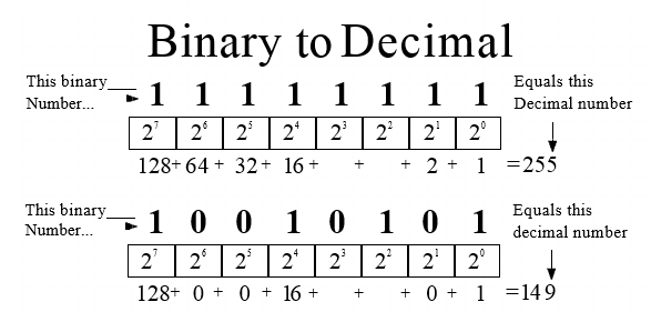
While you don’t need to be able to see 10010101 and intuitively know what human number it is, it’s important to understand that binary is more than capable of representing a larger-than-one value.
A note to Electrical Engineers
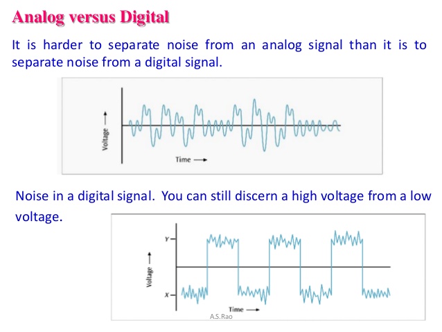
Unlike analog electronics which operate on continuous values, computer circuits operate on discrete values. This is necessary to avoid data corruption from noise in a circuit (noise is unwanted electrical signal, like unwanted background noise in a conversation).
Of all the possible discrete value number systems, a binary number system has the widest noise margin (gap between values) and is therefore the safest from electrical noise.
What’s in the Box?
Von-Neumann Architecture
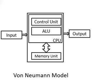
The Von-Neumann Architecture is a model for how computers look at a high level, with the CPU containing a Control Unit and ALU (Arithmetic Logic Unit) that are connected to a Memory Unit. The interaction of these blocks and the very basics of how they are implemented are the crux of this post.
Programs are stored in binary as instructions, and the control logic of the CPU reads in the program instruction by instruction and executes it. Instructions either operate upon data or control the control flow of the processor. Both operate using registers, special on-CPU memory that is very fast and used like a scratchpad. Data in memory needs to first be loaded into registers before it can be operated on.
The Input and Output blocks model any devices attached to the processor. A PC could be thought of having a Keyboard + Mouse input and Screen + Speaker output, while an airplane autopilot controller has thousands of sensor inputs and the planes physical controls as output.
Assembly Code
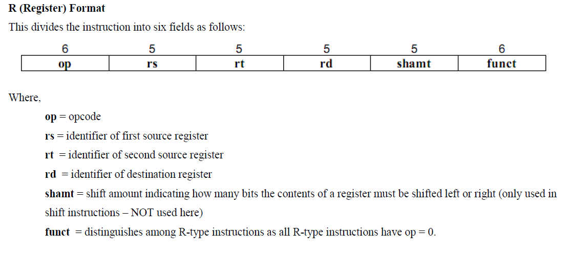
Instructions are stored in machine code, typically in 32-bit sections called words (in 64-bit machines, words are 64 bits). As shown in the above graphic the instruction is composed of several smaller bit-length values, which are used to encode what the instruction is for interpretation by the processor.
The Processor
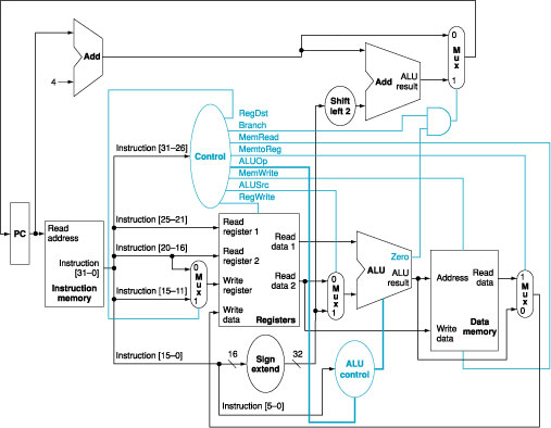
The control and data logic for a simple processor is laid out above. Control is blue, data is black.
The control logic handles reading instructions from memory, and decoding each instruction to appropriately control the passage of data through the processor. It’s also responsible for handling control-flow instructions, mainly conditions and jumps.
Once an instruction is loaded, the control signals set the addresses the register block should read from, what operation the ALU should perform, and where the result should be written back to memory. The logic of how these are implemented is complicated beyond the scope of this post, but can be found here.
Memory
SRAM
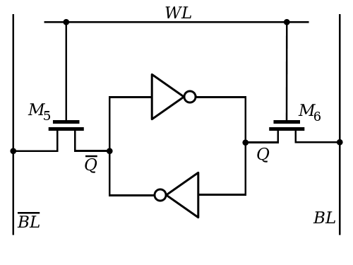
On chip registers and caches are built using two inverters feeding back into each other, which keeps a steady state. The two inverters are each built with two transistors, leaving one SRAM bit costing 6 transistors.
DRAM
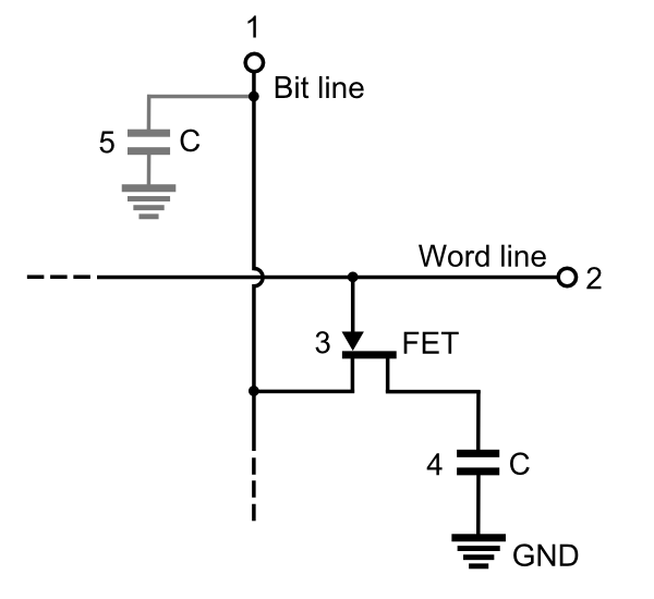
Memory cells in DRAM are built with one transistor and one capacitor, which stores a high or low value. The transistor is cutoff until the word line has a high voltage on it, at which point the stored voltage flows out into the bit line.
DRAM technology is slower than SRAM, and therefore makes little sense to put on the CPU. It makes more sense to make DRAM storage massive, and put it on a dedicated memory card. A conversation on the possibility of on-chip DRAM can be found here.
Storage
Hard Drives
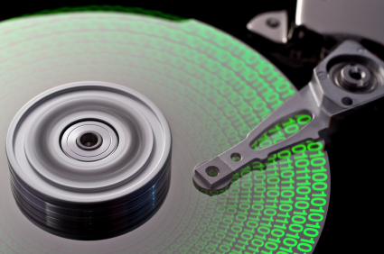
Hard drives store and load data from small magnetic wells on magnetic disks, similar to how CDs and magnetic tapes are used in other media. Because the data is stored by changing the magnetic state of the disk, data is stored even when the disk isn’t actively powered.
Keeping spinning disks in a portable device like a laptop is a bit dicey. Luckily, drives with no moving parts exist.
Solid State Drives

Solid state drives have no moving parts, and use flash gates like those above to store data by holding some permanent electric field in the floating gate. The gate is sandwiched with insulating silicon oxide, so it’s charge state doesn’t change when the drive is powered off.
This form of storage is much faster than a hard drive, in part because there aren’t mechanical components to wait on. Also, flash memory can be incorporated directly into a circuit, which allows tighter integration of storage and circuitry.
Implementing Logic Gates
Shrinking Computers
Digital logic can be implemented by any electrical device that exhibits a ‘switching’ behavior, meaning it can toggle between transmitting a signal and disconnecting that signal. In modern technology, transistors smaller than the mind can comprehend are laid out by the billions on single chips, but that development is a new one.
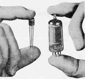 Vacuum Tube and Transistor. Note the physical transistor is smaller than it’s
packaging makes it seem.
Vacuum Tube and Transistor. Note the physical transistor is smaller than it’s
packaging makes it seem.
Far far back, in the beginning times, computers were built with vacuum tubes, the best switching device available at the time. Vacuum tubes were good at the time, but they were big, fragile, and had a heated element in them that burned tons of power.
Around the 1950’s, semiconductor technology was developed, and the first transistors were created. These transistors were much smaller than the vacuum tubes they replaced and required no heating element, allowing transistors to be packed more densely in designs.
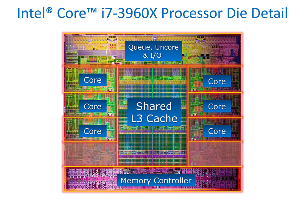 Billions of transistors in modern intel CPU. credit
Over the years, designers discovered that transistor sizes were consistently decreasing year-to-year, and that they could integrate multiple transistors on a single sheet of silicon. Not long after, the first single-chip CPUs were manufactured.
Nowadays, a single chip contains billions of transistors, and drastically outpaces the massive warehouse-scale computers of yore.
To drive home the scale of the improvements made, ENIAC weighed 30 tons, took up 1,800 square feet of space, and had 20,000 vacuum tubes. Using a modern 14nm manufacturing process 4.4 billion transistors can be fit into a square centimeter . Conservatively assuming we’ll need 10x the transistors to implement the same logic the tubes did, a transistor-based ENIAC could fit into a 20th of a square centimeter.
CMOS Logic
Complementary Metal-Oxide Semiconductor technology is used to implement logical gates in computers. The technology uses a PMOS-NMOS pair of transistors to connect the output to the high or low voltage. Only one transistor of the pair will be ‘switched’ on for any given input, which effectively means no current flows in a CMOS technology.
The above CMOS inverter produces an output of 1 for an input of 0, and output of 0 for and input of 1. This is because when the input is low, the PMOS (upper) transistor conducts and the NMOS (lower) transistor is an open circuit, connecting the output to the supply voltage. The opposite occurs for a high input.
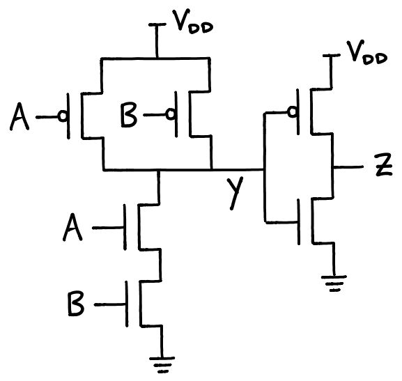
.PNG)
The above circuits are more complex CMOS circuits, which are less easily understood. Further reading on them can be found here. #Further Reading A similar article to this, more focused on logic gates and older forms of memory.